Confidence in every coordinate.

COORDINATE TRANSFORMATION TOOLS.

Work with multiple coordinate systems directly inside AutoCAD and BricsCAD

Transform existing CAD geometry between coordinate reference systems without leaving model space. GeoWizard applies official grid-based models within the correct geodetic context so legacy drawings can be aligned accurately with modern spatial reference frameworks.

Design data does not need to be exported to external GIS or survey platforms just to perform coordinate conversions. Geometry stays in place while its spatial reference is updated in a controlled and traceable way.

Where no single-step transformation exists, GeoWizard follows validated multi-step pathways to bring historic or regional datums into current project systems, keeping survey data, design models and deliverables spatially consistent.

Ribbon bar and command support are also included for fast, familiar access.

SURVEY DATA IMPORT.

Bring external coordinate data directly into your drawing environment

Survey coordinate lists from common ASCII formats can be turned into CAD geometry within minutes. Before import, the coordinate system of the source file is defined so new objects land in the correct spatial position the first time.

There is no need to pass files through separate office or GIS software just to make them usable in CAD. Field survey points, control mark data and consultant coordinate lists can be converted into points, linework or other objects through a structured import process.

The result is a direct path from survey file to working drawing, with spatial integrity preserved from the original dataset to the final design environment.

VERTICAL AND EPOCH SUPPORT.

Maintain consistency in height systems and time-dependent coordinates

Projects that depend on reliable elevation data require more than horizontal alignment alone. GeoWizard handles vertical reference considerations alongside coordinate transformations so height values remain consistent between survey inputs, design models and construction outputs.

Modern coordinate systems that reference a specific epoch can also be accounted for as part of the workflow. This is particularly relevant in regions affected by tectonic motion, where positional values may vary depending on the time frame of the data.

Treating vertical and epoch-related factors as part of the same spatial process reduces the chance of subtle but meaningful positional discrepancies between datasets collected at different times.

GEOREFERENCED IMAGE INSERTION

Add spatially aligned imagery directly into your drawing

Satellite or aerial imagery can be inserted into model space using real-world coordinates tied to the active coordinate system. The image becomes a spatially correct reference layer that reflects actual site conditions.

Because imagery is placed using coordinate control rather than manual scaling or alignment, it maintains its position when drawings are shared or reopened. Teams can review designs against a consistent visual backdrop without depending on live web map connections.

This approach supports clearer communication between survey, design and review teams by linking geometry to recognisable ground conditions.

GLOBAL COORDINATE SUPPORT

Work confidently with coordinate systems from around the world

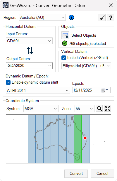
GeoWizard includes support for coordinate reference systems used across multiple countries and regions, enabling consistent handling of international project data within a single CAD environment. Regional profiles align with locally used systems, datums and terminology, helping users apply the correct spatial references without needing separate tools for different parts of the world.

Ready to get started?

Access GeoWizard today and bring accuracy and control to your coordinate and geospatial workflows.